The Mollier Diagram, officially called the Enthalpy-Entropy Diagram, is a vital device in thermodynamics for know-how and reading the homes and conduct of steam and different fluids. Named after the German engineer Richard Mollier, this diagram gives a graphical illustration of the relationships among enthalpy (H), entropy (S), and different thermodynamic homes inclusive of stress and temperature. It is specifically beneficial for engineers and scientists worried in designing and optimizing structures like steam turbines, refrigeration cycles, and air con structures.
The improvement of the Mollier Diagram represents a considerable milestone in thermodynamics. Richard Mollier, withinside the early twentieth century, brought this diagram to beautify the realistic utility of thermodynamic principles. His paintings enabled a greater intuitive and powerful evaluation of power ameliorations with the aid of using illustrating the modifications in enthalpy and entropy for the duration of diverse thermodynamic processes.
Basic Concepts of Thermodynamics
Understanding the Mollier Diagram calls for a stable hold close of essential thermodynamic concepts. Here, we cowl key phrases and definitions, homes of steam and refrigerants, and primary thermodynamic cycles to offer a basis for decoding and making use of the Mollier Diagram effectively.
Key Terms and Definitions
Thermodynamics: The department of physics that offers with the relationships among warmness, work, temperature, and power. It offers the standards governing the conduct of power and matter.
Enthalpy (H): A thermodynamic assets that represents the full warmness content material of a device. It is the sum of the inner power and the fabricated from strain and quantity (H = U + PV). Enthalpy is essential in studying power adjustments in strategies like heating and cooling.
Entropy (S): A degree of the ailment or randomness in a device. It represents the quantity of power in a device that isn’t to be had to do work. In thermodynamics, entropy is a key thing in figuring out the performance of warmth engines and refrigeration cycles.
Pressure (P): The pressure exerted in line with unit area. In thermodynamics, strain performs a sizable position in figuring out the country and segment of a substance.
Temperature (T): A degree of the common kinetic power of the debris in a substance. It affects the homes and conduct of substances and fluids.
Specific Heat (c): The quantity of warmth required to elevate the temperature of a unit mass of a substance through one diploma Celsius. Specific warmness varies with the substance and its segment.
Specific Volume (v): The quantity occupied through a unit mass of a substance. It is the reciprocal of density.
Work (W): The power transferred through a device to its environment or vice versa because of a extrade in quantity or strain.
Heat (Q): The power transferred among structures or environment because of a temperature difference.
Properties of Steam and Refrigerants
Steam:
Saturated Steam: Steam this is in equilibrium with liquid water at a given strain and temperature. It can exist as both saturated liquid or saturated vapor.
Superheated Steam: Steam this is heated past its saturation factor at a regular strain. It has a better enthalpy and is utilized in numerous engineering programs for advanced performance.
Critical Point: The temperature and strain at which steam and liquid water end up indistinguishable, called the crucial factor.
Refrigerants:
Refrigerant Properties: Refrigerants are materials utilized in refrigeration and air con structures to soak up and launch warmness. Key homes consist of boiling factor, freezing factor, latent warmness, and precise warmness.
Common Refrigerants: Examples consist of R-134a, R-22, and R-410A. Each refrigerant has wonderful thermodynamic homes appropriate for one-of-a-kind programs.
Components of the Mollier Diagram
The Mollier Diagram, or Enthalpy-Entropy Diagram, is a effective device used to visualise the thermodynamic homes of fluids. It includes numerous key additives that assist in expertise and reading numerous thermodynamic approaches. Here`s a breakdown of the number one additives of the Mollier Diagram:
Pressure-Entropy Diagram
Definition: The Pressure-Entropy (P-S) Diagram represents the connection among stress and entropy of a substance at numerous thermodynamic states.
Features:
Pressure Lines: These are curves at the diagram that display steady stress situations. They assist in expertise how stress modifications with entropy for the duration of exceptional approaches.
Phase Boundaries: The diagram consists of traces that demarcate the limits among exceptional phases (solid, liquid, and fueloline). The limitations imply the situations below which segment modifications arise.
Isentropic Processes: Lines or curves representing approaches in which entropy stays steady. These approaches are adiabatic and arise in mills and compressors.
Usage:
Steam Turbine Analysis: Helps in comparing the overall performance of steam mills with the aid of using displaying how stress and entropy alternate for the duration of expansion.
Refrigeration Systems: Useful for assessing the overall performance of refrigeration cycles with the aid of using monitoring stress and entropy modifications via the cycle.
Enthalpy-Entropy Diagram
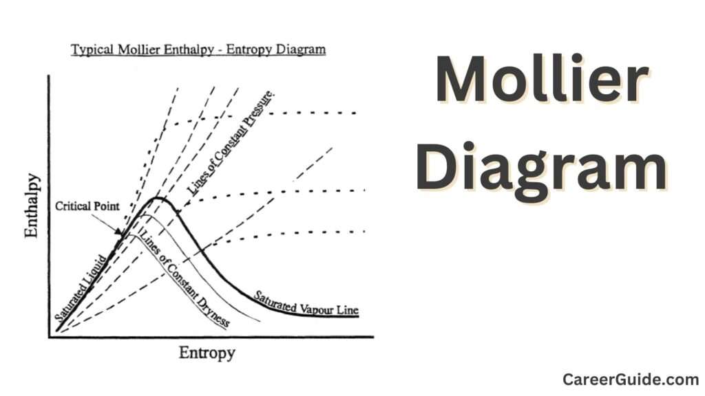
Definition: The Enthalpy-Entropy (H-S) Diagram, additionally referred to as the Mollier Diagram, indicates the connection among enthalpy and entropy. It is the maximum not unusualplace shape of the Mollier Diagram.
Features:
Enthalpy Axis: The horizontal axis represents enthalpy, that is a degree of the overall warmness content material of the substance.
Entropy Axis: The vertical axis represents entropy, that is a degree of the ailment or randomness.
Saturation Lines: Curves that separate the liquid and vapor phases. They imply the enthalpy and entropy at which segment modifications arise.
Isentropic Lines: Lines of steady entropy, beneficial for reading adiabatic approaches.
Usage:
Heat Exchanger Design: Assists in designing warmness exchangers with the aid of using displaying the enthalpy modifications of fluids.
Cycle Analysis: Essential for reading thermodynamic cycles including Rankine and refrigeration cycles, imparting perception into power adjustments and efficiency.
Temperature-Entropy Diagram
Definition: The Temperature-Entropy (T-S) Diagram depicts the connection among temperature and entropy for a given substance.
Features:
Temperature Axis: The horizontal axis represents temperature.
Entropy Axis: The vertical axis represents entropy.
Phase Boundaries: Similar to the P-S diagram, the T-S diagram consists of segment limitations indicating the transitions among solid, liquid, and fueloline phases.
Isothermal Processes: Lines or curves that constitute approaches happening at steady temperature.
Usage:
Thermodynamic Processes: Useful for visualizing approaches like heating, cooling, and segment modifications.
Cycle Analysis: Helps in expertise cycles with the aid of using displaying how temperature and entropy vary, making it simpler to assess overall performance and efficiency.
Understanding the Mollier Diagram
The Mollier Diagram, or Enthalpy-Entropy Diagram, is an vital device in thermodynamics for visualizing the conduct of fluids in diverse approaches. To correctly use the Mollier Diagram, it`s critical to recognize its axes, scales, and the exceptional forms of approaches represented on it. Here`s an in depth study every aspect:
Axis and Scales
Enthalpy (H) Axis:
Position: Typically the horizontal axis of the diagram.
Units: Measured in kilojoules consistent with kilogram (kJ/kg).
Purpose: Represents the entire warmth content material of the fluid. Higher values suggest better thermal energy.
Entropy (S) Axis:
Position: Typically the vertical axis of the diagram.
Units: Measured in kilojoules consistent with kilogram consistent with Kelvin (kJ/kg·K).
Purpose: Represents the disease or randomness of the fluid. Higher entropy values suggest extra disease.
Scales:
Enthalpy Scale: Shows the variety of enthalpy values for the fluid, which includes areas of saturated liquid, saturated vapor, and superheated vapor.
Entropy Scale: Shows the variety of entropy values, which includes adjustments for the duration of section transitions and isentropic approaches.
Phase Boundaries:
Saturation Lines: Curves that separate exceptional levels (liquid and vapor). They suggest the situations at which section adjustments occur.
Critical Point: The factor at which the difference among liquid and vapor levels disappears.
Isentropic Processes
Definition: An isentropic procedure is a thermodynamic procedure for the duration of which the entropy of the fluid stays consistent. This means that the procedure is adiabatic (no warmth transfer) and reversible.
Characteristics:
Representation: On the Mollier Diagram, isentropic approaches are proven as vertical lines (consistent entropy) or almost vertical curves relying at the particular fluid.
Application: Commonly utilized in reading mills and compressors in which the procedure is idealized as adiabatic and reversible.
Usage:
Turbine Analysis: Helps in figuring out the performance and overall performance of steam mills.
Compressor Analysis: Useful for comparing the overall performance of compressors in refrigeration and air con systems.
Isobaric Processes
Definition: An isobaric procedure happens at a consistent strain. During this procedure, the strain of the fluid stays unchanged at the same time as different houses together with enthalpy and entropy might also additionally vary.
Characteristics:
Representation: On the Mollier Diagram, isobaric approaches are represented as horizontal lines (consistent strain).
Phase Changes: In isobaric approaches, section adjustments (e.g., boiling or condensation) may be visualized as horizontal moves alongside the saturation lines.
Usage:
Heating/Cooling: Analyzes approaches like heating or cooling of fluids in warmth exchangers or boilers.
Phase Transitions: Helps in expertise how a fluid transitions among levels at consistent strain.
How to Read the Mollier Diagram
Reading and decoding the Mollier Diagram (Enthalpy-Entropy Diagram) is critical for reading and optimizing thermodynamic structures. This manual offers a step-with the aid of using-step method to expertise facts factors, finding segment barriers, and making use of the diagram to real-global scenarios.
Interpreting Data Points
Identify Enthalpy and Entropy Values:
Enthalpy (H): Locate the enthalpy cost at the horizontal axis. This cost represents the entire warmness content material of the fluid.
Entropy (S): Locate the entropy cost at the vertical axis. This cost represents the ailment or randomness withinside the machine.
Plotting Data Points:
Locate Data Points: On the diagram, plot the facts factors similar to unique enthalpy and entropy values.
Determine State: Identify the kingdom of the fluid (saturated liquid, saturated vapor, superheated vapor) primarily based totally on the location of the facts factor relative to the segment barriers.
Analyze Changes:
Process Analysis: Track adjustments in enthalpy and entropy to recognize how the machine transitions among special states (e.g., from liquid to vapor).
Process Efficiency: Evaluate the performance of strategies with the aid of using reading how the enthalpy and entropy values extrade at some stage in special thermodynamic cycles.
Locating Phase Boundaries
Saturation Lines:
Liquid-Vapor Boundary: The saturation traces at the Mollier Diagram separate the saturated liquid area from the saturated vapor area.
Critical Point: The factor wherein the saturation traces converge, indicating the crucial temperature and pressure. Beyond this factor, the liquid and vapor stages are indistinguishable.
Identify Phase Regions:
Saturated Liquid: The area to the left of the saturation line wherein the fluid is in a liquid kingdom.
Saturated Vapor: The area to the proper of the saturation line wherein the fluid is in a vapor kingdom.
Superheated Vapor: The location past the saturation vapor line, indicating a kingdom wherein the fluid is heated past its boiling factor.
Phase Transition:
Heating/Cooling: Follow the segment barriers to look how the fluid transitions among special states at some stage in heating or cooling strategies.
Using the Diagram for Real-World Applications
Analyzing Thermodynamic Cycles:
Rankine Cycle: Use the Mollier Diagram to research the overall performance of steam mills and energy plant life with the aid of using monitoring adjustments in enthalpy and entropy thru the cycle.
Refrigeration Cycle: Evaluate the overall performance of refrigeration structures with the aid of using analyzing the enthalpy and entropy adjustments at some stage in evaporation, compression, condensation, and expansion.
Designing Heat Exchangers:
Heat Transfer: Use the diagram to decide the enthalpy adjustments of fluids passing thru warmness exchangers, assisting to layout structures that maximize warmness switch performance.
Optimizing Performance:
Efficiency Analysis: Assess the performance of mills, compressors, and different thermodynamic gadgets with the aid of using reading the enthalpy and entropy adjustments and evaluating them to best strategies.
Troubleshooting Systems:
System Performance: Identify troubles in thermodynamic structures with the aid of using monitoring deviations from predicted enthalpy and entropy values, assisting to diagnose and remedy overall performance problems.
Applications of Mollier Diagram
The Mollier Diagram, or Enthalpy-Entropy Diagram, is a useful device in thermodynamics, particularly for reading and optimizing numerous structures concerning fluids. Below are key packages of the Mollier Diagram throughout special fields:
Steam Turbine Analysis
Performance Evaluation:
Cycle Analysis: The Mollier Diagram enables in reading the Rankine cycle, that’s the idea for steam turbine operation. By monitoring enthalpy and entropy modifications thru the cycle, engineers can verify the overall performance and performance of the turbine.
Efficiency Calculations: Engineers use the diagram to calculate thermal performance through evaluating the enthalpy modifications throughout the turbine with the enter strength.
Design Optimization:
Turbine Design: The diagram aids in designing mills through supplying insights into the most advantageous running conditions, together with strain and temperature, to maximise performance and output.
Load Management: Helps in figuring out how the turbine responds to special masses through visualizing how enthalpy and entropy extrade below various operational conditions.
Troubleshooting:
Performance Issues: Identifies deviations from predicted overall performance through evaluating real information factors with best enthalpy and entropy modifications, helping in diagnosing and correcting troubles.
Refrigeration Systems
System Design:
Cycle Optimization: The Mollier Diagram is used to layout and optimize refrigeration cycles through reading enthalpy and entropy modifications all through evaporation, compression, condensation, and enlargement.
Component Sizing: Assists in sizing additives together with compressors, condensers, and evaporators through supplying specified facts at the thermodynamic houses of the refrigerant.
Efficiency Assessment:
Coefficient of Performance (COP): Engineers use the diagram to calculate the COP of refrigeration structures through reading the ratio of warmth eliminated to paintings enter.
Performance Monitoring: Helps in tracking and enhancing the performance of refrigeration structures through visualizing how nicely the device operates in comparison to best conditions.
Troubleshooting:
Identifying Faults: Detects inefficiencies or faults in refrigeration structures through evaluating real device overall performance with theoretical overall performance at the Mollier Diagram.
Air Conditioning Systems
System Design and Optimization:
Cycle Analysis: The Mollier Diagram enables layout and optimize aircon cycles through reading the enthalpy and entropy modifications all through the cooling process.
Component Design: Assists in designing aircon additives together with enlargement valves, compressors, and evaporators through supplying insights into the thermodynamic houses of the refrigerant.
Performance Evaluation:
Efficiency Metrics: Evaluates the performance of aircon structures through calculating metrics like COP and strength intake primarily based totally at the enthalpy and entropy information from the diagram.
Temperature Control: Helps in information how temperature modifications have an effect on the overall performance of the aircon device, helping in higher manipulate and regulation.
Troubleshooting and Maintenance:
System Performance: Identifies and resolves troubles in aircon structures through evaluating real overall performance with theoretical expectancies at the Mollier Diagram.
Energy Consumption: Helps in diagnosing excessive strength intake troubles through reading deviations in enthalpy and entropy values.
Mollier Diagram for Different Working Fluids
The Mollier Diagram, or Enthalpy-Entropy Diagram, may be tailored to diverse operating fluids to visualise their thermodynamic homes and examine specific processes. Here`s how the diagram applies to specific fluids:
Water and Steam
Characteristics:
Phase Boundaries: The Mollier Diagram for water and steam consists of awesome segment limitations that separate the liquid and vapor levels. The diagram prominently capabilities the saturation traces in which water transitions among liquid and vapor states.
Critical Point: Water`s essential factor is a key feature, past which the difference among liquid and vapor levels disappears. On the diagram, that is represented via way of means of the convergence of the saturation traces.
Applications:
Steam Turbine Analysis: The diagram is appreciably used for studying steam generators in electricity plants. It enables in comparing the steam cycle performance and designing generators to optimize power conversion.
Boilers and Condensers: Engineers use the Mollier Diagram to layout and optimize boilers and condensers via way of means of monitoring the enthalpy and entropy adjustments of steam at some point of heating, cooling, and segment adjustments.
Example:
Rankine Cycle: In a Rankine cycle, the Mollier Diagram indicates the steam increasing in a turbine, condensing in a condenser, after which being pumped returned to the boiler. The enthalpy and entropy adjustments at every degree are essential for performance analysis.
Refrigerants (e.g., R-134a, R-22)
Characteristics:
Phase Boundaries: For refrigerants like R-134a and R-22, the Mollier Diagram consists of segment limitations precise to every refrigerant. These limitations suggest the situations beneathneath which the refrigerant adjustments segment from liquid to vapor and vice versa.
Critical Point: Each refrigerant has its very own essential factor, in which the liquid and vapor levels grow to be indistinguishable. This is an crucial thing of the diagram for designing structures that function close to or above those essential situations.
Applications:
Refrigeration Systems: The Mollier Diagram is used to layout and optimize refrigeration structures, which include compressors, condensers, and evaporators. It enables in know-how the thermodynamic homes of refrigerants at some point of the refrigeration cycle.
Air Conditioning: Similar to refrigeration, the diagram aids in studying and optimizing aircon structures via way of means of monitoring the enthalpy and entropy adjustments of refrigerants.
Example:
Vapor Compression Cycle: In a vapor compression refrigeration cycle, the Mollier Diagram indicates the refrigerant present process compression, condensation, expansion, and evaporation. It enables in visualizing the overall performance and performance of the refrigeration system.
Construction of Mollier Diagram
Creating a Mollier Diagram entails numerous key steps, along with graphical representation, facts collection, and the usage of software program tools. Here`s an in depth manual on the way to assemble a Mollier Diagram with out that specialize in particular numerical values.
Graphical Representation
Define the Axes:
Enthalpy (H): The horizontal axis represents enthalpy. This suggests the overall warmth content material of the fluid.
Entropy (S): The vertical axis represents entropy. This suggests the diploma of sickness or randomness withinside the system.
Plot Phase Boundaries:
Saturation Lines: Draw strains at the diagram that separate the areas wherein the fluid is in a saturated liquid kingdom from wherein it’s miles in a saturated vapor kingdom. These strains mark the segment alternate boundaries.
Critical Point: Identify the factor wherein the saturation strains converge. This is wherein the fluid transitions from a distinguishable liquid and vapor segment to a supercritical kingdom.
Include Phase Regions:
Saturated Liquid: The place to the left of the saturation strains represents the fluid in its liquid segment.
Saturated Vapor: The place to the proper of the saturation strains represents the fluid in its vapor segment.
Superheated Vapor: Beyond the saturation vapor line, the vicinity wherein the vapor is heated past its boiling factor.
Add Isentropic, Isothermal, and Isobaric Lines:
Isentropic Lines: Vertical strains that constitute regular entropy. These strains are beneficial for studying strategies wherein no warmth is transferred.
Isothermal Lines: Curved strains that constitute regular temperature. They assist examine strategies taking place at a regular temperature.
Isobaric Lines: Horizontal strains representing regular stress. These strains display how the fluid`s houses alternate beneathneath regular stress conditions.
Mark Key Points and States:
Boiling and Condensation Points: Indicate the temperatures and enthalpies at which the fluid transitions among liquid and vapor phases.
Expansion and Compression Points: Highlight the modifications in enthalpy and entropy throughout the enlargement and compression strategies.
Experimental Data Collection
Obtain Thermodynamic Data:
Steam and Refrigerant Tables: Collect facts on enthalpy, entropy, temperature, and stress for the fluid being analyzed from to be had thermodynamic tables.
Perform Laboratory Measurements:
Experimental Testing: Conduct experiments to degree the thermodynamic houses of the fluid at numerous temperatures and pressures. This entails figuring out the enthalpy and entropy beneathneath special conditions.
Use Calibration and Reference Data:
Reference Data: Use mounted reference facts to make certain the accuracy of the values plotted at the diagram.
Calibration: Ensure that dimension devices are nicely calibrated to offer correct facts.
Validate Data:
Cross-Verification: Check experimental facts in opposition to theoretical values or different dependable reassets to verify accuracy.
Limitations of Mollier Diagram
1. Evolving Responsibilities
Expanded Legal Advisory Role:
Increasing involvement in advising on rising felony troubles together with statistics privacy, cybersecurity, and worldwide law.
Policy Formulation:
Collaborating intently with policymakers to draft regulation that aligns with evolving societal wishes and international standards.
Crisis Management:
Developing knowledge in dealing with felony crises, along with herbal disasters, public fitness emergencies, and country wide safety demanding situations.
International Engagement:
Enhancing participation in worldwide felony boards and negotiations to persuade international felony norms and treaties.
Public Advocacy:
Advocating for public hobby litigation and social justice reasons to uphold constitutional rights and liberties.
2. Technological Advancements
Legal Tech Integration:
Adopting Artificial intelligence and gadget getting to know gear for felony research, case analysis, and file automation.
Data Analytics:
Utilizing massive statistics analytics to expect felony trends, optimize case strategies, and decorate decision-making processes.
Remote Proceedings:
Embracing digital court docket technology for faraway hearings, decreasing logistical demanding situations and improving get entry to to justice.
Cybersecurity Measures:
Implementing sturdy cybersecurity protocols to protect touchy felony records and save you statistics breaches.
Digital Collaboration:
Facilitating seamless collaboration amongst felony groups and stakeholders thru stable on-line systems and cloud-primarily based totally solutions.
Frequently Asked Questions (FAQs)
Q1. What is a Mahadhivakta?
A Mahadhivakta is the best-ranking prison officer in a state or united states, chargeable for representing the authorities in prison matters and providing legal recommendation.
Q2. What are the qualifications required to grow to be a Mahadhivakta?
Qualifications normally include extensive legal information, a law degree from a diagnosed organization, many years of criminal practice, and club in the kingdom bar association.
Q3. What are the important thing obligations of a Mahadhivakta?
Key responsibilities encompass representing the nation in courtroom, advising the authorities on prison matters, drafting criminal files, and supervising prison teams.
Q4. How is a Mahadhivakta appointed?
A Mahadhivakta is typically appointed via nomination through the government, followed by way of approval from applicable government along with the governor or president, and formal appointment thru an reliable notification.
Q5. What demanding situations do Mahadhivaktas face?
Mahadhivaktas often face challenges together with political pressures, heavy workload, managing impartiality, and navigating complicated felony and ethical dilemmas.